
VlamShield · Technical data · PV mounting system
VlamShield PV mounting system
Fire-protection layer, roof protection, load spreading and usable ballast weight in one connected structure. Data per board and m², including a complete weight example with a PV module. Date 29.09.2026 · Issue 0.4.
- Example incl. 22 kg module, no extra ballast
- 22.85 kg/m²
- WEER board contribution
- 12 kg/m²
- Reference area per board
- 2.2625 m²
01 · System assembly
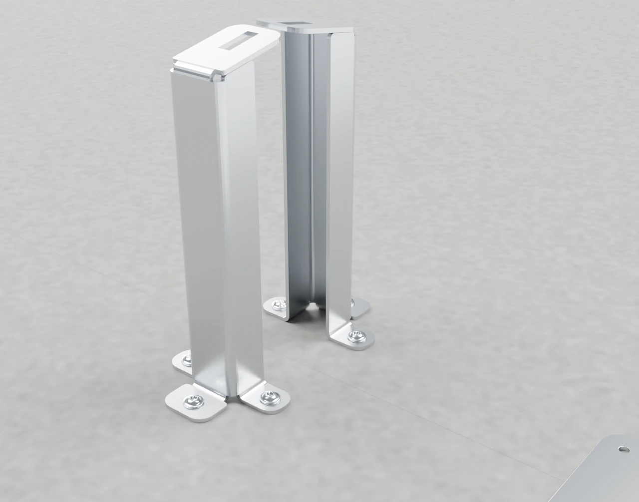
WEER boards above the roof waterproofing; high and low module supports; flat connectors at board joints; M6×17 screws installed from above into stainless steel inserts on the board underside; black module clamps.
Material specification for supports and connectors: V4A stainless steel, for example grade 1.4404. Metal weights below are calculated from CAD using a density of 8,000 kg/m³; they are not measured production weights.
Adjacent boards can be joined with flat connectors into larger continuous fields. Maintenance paths and breaks are planned for each project. Connector quantities and positions depend on field edges and board joints.
02 · Individual board and component dimensions
| Property | Individual board / component |
|---|---|
| Board dimensions | 1,810 × 1,250 × 15 mm |
| Board area | 2.2625 m² |
| WEER area weight | approximately 12 kg/m² at 7% moisture |
| WEER weight per board | calculated approximately 27.15 kg |
| High module support: bounding dimensions | approximately 96 × 87.6 × 229 mm |
| Low module support: bounding dimensions | approximately 40 × 139.7 × 31.5 mm |
| Flat connector | 120 × 120 × 3 mm |
| Board screw | M6×17; head Ø approximately 13.6 mm; head height 3.3 mm |
| Permitted module external dimensions (length × width) | exclusively 1,762 × 1,134 mm |
| Frame height in the CAD example | 30 mm; check actual frame height and clamping |
| Module inclination in CAD | 10° |
Support dimensions: external bounding dimensions from CAD. The board format applies to the mounting system. Also check module frame height, clamping zones and installation requirements.
03 · Complete weight including module – worked example
Reference: one 1,810 × 1,250 mm board with one module, giving 2.2625 m² of covered board area. Module weight is assumed at 22.0 kg: a rounded planning allowance, not a statistical average of all modules.
| Component | Allowance per board / module | Weight |
|---|---|---|
| WEER board, 15 mm | 2.2625 m² × 12 kg/m² | 27.150 kg |
| High supports | 2 × 0.56251 kg | 1.125 kg |
| Low supports | 2 × 0.15382 kg | 0.308 kg |
| Flat connectors, allocated share | 2 × 0.33762 kg | 0.675 kg |
| M6×17 screws | 18 × 0.005079 kg | 0.091 kg |
| Stainless steel inserts | 18 × 0.003366 kg | 0.061 kg |
| Complete module clamps including fasteners | 4 × 0.071 kg | 0.284 kg |
| PV module | Assumed 22.0 kg | 22.000 kg |
| Total without extra ballast | Sum using unrounded CAD values | approx. 51.694 kg |
| Total per covered board area | 51.694 kg ÷ 2.2625 m² | approx. 22.85 kg/m² |
Connector allowance: two whole flat connectors per board as an allocated field share, not a fixed four-module unit or a prescribed connection layout. Ten screw/insert pairs fix the supports; eight further pairs correspond to two connectors with four fixings each. Shared connectors are counted only once in the complete array.
Clamps: manufacturer weight of 0.071 kg per complete SL Rack 96162-01 end clamp including its fastener; do not count that fastener again. Check the actual clamp arrangement. Module: rounded 22 kg assumption; a Trina Vertex S DE09R measuring 1,762 × 1,134 × 30 mm is listed at 21.8 kg. No mandatory module brand is specified.
Metal components: CAD volume × 8,000 kg/m³ for V4A stainless steel, not measured production weights. WEER approximately 12 kg/m² at 7% moisture. Rounding differences may occur. 22.85 kg/m² corresponds to approximately 0.224 kN/m² dead load, before load factors, snow or wind.
Module area: 1.762 × 1.134 = 1.998108 m², giving approximately 25.87 kg/m² on that basis. This is not the horizontal projection of the tilted module. The stated system figure uses covered board area, excluding unoccupied roof areas and maintenance aisles.
Project figure = total boards, supports, actual connectors/fasteners, clamps, modules and extra ballast ÷ covered board area. Account separately for other roof loads such as cable trays. Each extra kg of module weight adds approximately 0.442 kg/m² in this example.
04 · Multiple functions, ballast and load spreading
WEER combines a mineral fire-protection layer, weather-resistant roof protection and a broad bearing surface for the attached mounting system. The mechanical connection also makes board self-weight available as a ballast contribution. The same weight serves several purposes.
The load path runs from the module through clamps and supports, screws and inserts into the board. Flat connectors transfer forces between neighbouring boards. The weight that can be credited against uplift and sliding depends on verified connection strength, board behaviour, friction and system design.
A larger effective bearing area can reduce local pressure peaks. This does not establish uniform load distribution over the entire board or array: stiffness, joints, unevenness, insulation and actual bearing conditions all matter. Load spreading does not replace verification of roof capacity or insulation compressive performance.
Available spare capacity must be established from the existing structural assessment and roof condition; it is not guaranteed for every roof. Safety factors and required snow/wind allowances are not spare capacity available for PV. Total weight, load positions and load combinations remain decisive.
Extra ballast may be required for high wind exposure, tall buildings or unfavourable edge and corner zones. Larger connected arrays may offer a more favourable structural arrangement but do not replace wind verification. The project-specific design determines whether the board weight is sufficient. The design aims to use existing board weight efficiently towards the ballast requirement.
05 · Connection and assembly principle
1. Prepare the board layout
Arrange WEER boards to the designed roof and module layout. Keep drainage and maintenance routes clear.
2. Connect metal components
Position high and low supports and flat connectors. Insert M6×17 screws from above through the metal components into the threaded inserts on the underside.
3. Secure modules
Position only modules with external dimensions of 1,762 × 1,134 mm (length × width) on the supports and secure them with the specified clamps. Observe the chosen module's clamping zones and installation requirements.
Tightening torques, permissible connection loads, edge distances and wind restraint must be established in the project technical documentation; they cannot be determined from the visualisation.
06 · Material and project design
The mineral WEER board has an A1 reaction-to-fire classification as a construction material. This does not classify or approve the entire PV mounting system.
WEER is intended for direct installation on PVC-P, mineral-surfaced bitumen, PIB and TPO/FPO. Assess roof condition and drainage for each project. Permitted connection loads, wind restraint and load transfer follow from the technical verification of the specific build-up.